Happy New Year!
I hope that 2012 is a safe and wonderful new year for everyone.
New projects and designs for 2012. Just put the finishing touches on my music project (gebrochene augen) release Cellar, and right now am in the works to get it electronically released on iTunes, Spotify, and Amazon for purchase and listening.
Stay tuned, it should be an exciting year!
Brian
Saturday, December 31, 2011
Thursday, November 24, 2011
YAMAHA FM Data Modification
I figured I would post some insights on how to make some of the modifications I do to keyboards. In particular, presented here, are some tips for the Yamaha keyboards that use a FM chips. Some of the keyboards and chips are:
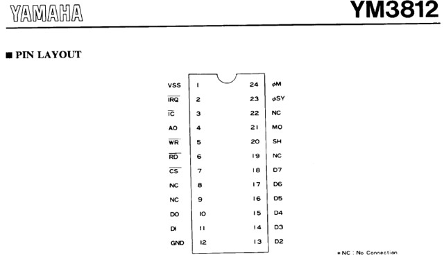
1. Check to make sure the Yamaha keyboard has one of these FM chips (like above), identify the chip number and get the pin outs. The pin outs of interest will be labeled D0, D1, ... D7. There are typically 8 data lines and these data lines connect to another chip in the circuit. For example, the YM3812 chip:
 2. Follow the traces on the circuit board from the FM chip to its destination, usually to a processing chip (or main chip, DAC) like XC194A0. Take pictures or make notes of where the traces lead to and what components may be inline (like a jumper or sometimes a resistor).
 As seen above, the RED indicated the FM chip and the BLUE indicates the main chip. You can see the traces from the FM to main chip With this keyboard jumpers can be see at the left of the FM chip (2nd and 3rd going right to left).
 Above is an example of where to cut for 6 of the 8 data lines. Note these are directly connected to the processing chip.
4. With the traces cut it is now time to reconnect the lines with wires and switches. You can solder new connections on the bottom of the board or directly to the pins of the FM chip on top; whatever you are comfortable and experienced with. I use colored wire so each data line has a specific color. This color coding keeps the project organized and easy to reference if additional modifications involve these points.
 Blue and Red wires connected where jumpers used to reside.


 Patch points used above.
 Good luck!
Disclaimer: I cannot be responsible for the outcome of the modification, you are doing this at your own risk. Circuit bending is part experimentation and part electrical engineering. These modifications made were not intended during the engineering and designing phase from the manufactures, so we each have to take responsibility for our own mistakes, or successes : ) .
- PSR-6, YM2413
- PSR-11, YM3812
- PSS-140, YM2420
1. Check to make sure the Yamaha keyboard has one of these FM chips (like above), identify the chip number and get the pin outs. The pin outs of interest will be labeled D0, D1, ... D7. There are typically 8 data lines and these data lines connect to another chip in the circuit. For example, the YM3812 chip:

3. With the traces marked or identified, cut them with a razor blade or Exacto knife; this must be sharp and precise. Alternatively, if there are jumpers used, desolder the jumpers and use the existing placement holes for you new connections.

4. With the traces cut it is now time to reconnect the lines with wires and switches. You can solder new connections on the bottom of the board or directly to the pins of the FM chip on top; whatever you are comfortable and experienced with. I use colored wire so each data line has a specific color. This color coding keeps the project organized and easy to reference if additional modifications involve these points.


The remaining 6 connections were soldered carefully to the chip pins.
5. Now connect each color wire to a single switch, a SPDT switch (ON/ON). I keep the FM wires all on the same poles of every data line. This way if other modifications are done it is easy to follow and make connections. Keep the wires together in two bundles with zip ties.


In some cases the keyboard lends well to using patch points. With this patch cables make the connection and this gives the ability of switching, mixing and blending data lines. you can experiment with this once all the new connections are made.

6. With all the connections made, test the modifications and make sure that when the switches are ON the data line from the FM chip to the processing chip is connected. Selecting the switch OFF will disconnect the data and this is where the fun begins. Once all connections are correct, otherwise make the corrections, I usually apply a bead of hot glue to the new soldered points. This way during assembly if the new wires are in a position where they may have a slight stress point they will not become bent or break off.

Disclaimer: I cannot be responsible for the outcome of the modification, you are doing this at your own risk. Circuit bending is part experimentation and part electrical engineering. These modifications made were not intended during the engineering and designing phase from the manufactures, so we each have to take responsibility for our own mistakes, or successes : ) .
Wednesday, November 2, 2011
WASP VCF Clone
I recently made a WASP VCF clone custom for a client.

Demo Video.
This Voltage Controlled Filter features 4 filter settings (NP, BP, HP and LP) along with distortion. Inputs and Outputs are 1/4" Mono Jacks, and it has an Input Gain control. Signals routed to this unit have Frequency Cut-Off and Resonance Controls for each of the 4 filters. Distortion works at any setting.
Tuesday, October 25, 2011
Wednesday, October 12, 2011
Updates
I have now started listing on Etsy, link below. A few items are listed now, more to come. Check it out!
FrankenMusik on Etsy
I will also list my standard builds on the Monster Box page. I have been building them in case aluminum enclosures which have a nice sturdy feel, work well as hand held units or on a desktop/work staton. Colors can be changed and of course I can customize the sounds/circuits as you so desire.
Effects/Filter/Sequencers: these units are available too! Samples to be loaded later, but please feel free to contact me any time.
Sunday, September 18, 2011
Steampunk Synth
This represents my latest work, a Steam Punk Synth. I spent a lot of time in the layout and design of this unique instrument. What once was an old Westinghouse Volt meter now is the enclosure for a square wave based analog synthesizer.

Accented with brass fasteners and hand crafted control knobs.


Complete with 1/4" audio output jack, volume control, input jack (7-9VDC), ON/OFF switch and three controls for Frequency, Rate and Choke.
Additional video soon to be added.

Accented with brass fasteners and hand crafted control knobs.


Complete with 1/4" audio output jack, volume control, input jack (7-9VDC), ON/OFF switch and three controls for Frequency, Rate and Choke.
Additional video soon to be added.
Thursday, September 8, 2011
PSS-270 Video
Here is the video of the Yamaha PSS-270:
Presented on this keyboard are the best (from what I found) of the available --circuit bent--modifications. The FM Data line modification interrupts the data between the FM chip (YM2413) and the XC194AO chip. By cutting off and selecting different Voices, altered sounds, tones and drones can be generated. It also works on the Rhythm section. The LFO mod was the last bend found during my search of the circuit board. By using various some caps I can alter the tone and range of tone with the control (potentiometer). The LED's' light up once this data is transfered from one part of the corcuit back in to the XC194AO chip. This mod is the Top left knob and switch (with RED and YELLOW LED's).
I'll post additional information on the FM modification later. I get questions often regarding this; it works on many YAMAHA series and not that difficult.
Monday, September 5, 2011
Circuit Bent Yamaha PSS-270
I just finished this Yamaha PSS-270 keyboard.

This build includes the FM data line modification via 8 switches, distortion glitch--one switch, 2 data scrambler channels (with LED indicators)--switch and knob controls, filter--switch and knob controls, 2-stage drone/LFO modification--switch and knob controls.


This build includes the FM data line modification via 8 switches, distortion glitch--one switch, 2 data scrambler channels (with LED indicators)--switch and knob controls, filter--switch and knob controls, 2-stage drone/LFO modification--switch and knob controls.


Sunday, July 24, 2011
Elmo's World Phone
I could not resist when I saw it at; I had to bend this phone.
Circuit Bent Elmo's World Phone

 Mattel did not leave much room for me to work with, so thanks to small components (potentiometers, switches etc) and a Dremel tool, I was able to outfit Elmo with these much needed effects!
Check out the video:
Circuit Bent Elmo's World Phone

This Elmo phone has a pitch control (yellow knob), a 1/8" audio output jack, audio selector switch, distortion and loop/drone glitch. The drone and distortion operate from the same toggle switch. A three position switch ((ON)/OFF/ON) is used to select between the two glitches. The Drone effect is activated with the momentary position as it only takes the slight signal to put Elmo in a crazy state.

Check out the video:
The pitch potentiometer completely replaces the pitch resistor on the circuit board. There are several bend points that affect his pitch, but I saw no sense in repeating the same thing. The distortion and drone effect mainly feed from the audio portion of the circuit but routed with some added capacitors and resistors of choice.
Sunday, July 10, 2011
Circuit Bent Elmo
This Elmo turned out great.

This Elmo has had the following improvements:


This Elmo has had the following improvements:
- Pitch Control (Red Knob)
- Pitch Control Switch: ON/OFF(ON)
- 1/8" Audio Output Jack
- Audio Selector Switch (Internal Speaker/Audio Out)
- Power Starve (Blue Knob)


Thursday, July 7, 2011
Vtech Alphabet Desk
Circuit Bent Vtech Alphabet Desk

Modified toy to generate some unique sounds and textures. Outfitted with a 1/4" output jack, volume control, output signal LED (red), glitch switch and a dual NAND gate distortion/oscillator function.


Demo Video:

Modified toy to generate some unique sounds and textures. Outfitted with a 1/4" output jack, volume control, output signal LED (red), glitch switch and a dual NAND gate distortion/oscillator function.


I made use of some industrial limit switches to activate the glitches. I found the lever offered a bit more control in how lightly the switches are activated; particularly with the switch at the top as this activates a loop once depressed and also alters the pitch and can mix up the sounds. Also, this glitch offers some steady drones. The switch on the right stutters and repeats the sounds/voices when activated at the same time as one of the Vtech buttons.
The NAND gate effect has its signal routed from two sources on the circuit board, one of them is the audio output signal. This offers heavy distortion on the voices and sounds.
Demo Video:
Thursday, June 30, 2011
Wednesday, June 29, 2011
Circuit Bent Casio SK-1
A true classic keyboard from the 80's. This circuit bent Casio SK-1 offers a huge range of sounds and textures. This is truly a must have instrument for any studio or live performance; as long as the sounds suite your music taste :).


This one will be offered on eBay once I get the video posted and some sound samples loaded.
Stay tuned!


This one will be offered on eBay once I get the video posted and some sound samples loaded.
Stay tuned!
Sunday, June 12, 2011
Circuit Bent YAMAHA PSR-22
Latest keyboard bend, Yamaha PSR-22.
 This keyboard is equipped with 15 modifications.
 PSR-22, close up.


 With the modifications to this keyboard endless sounds and random noises can be generated. This keyboard also goes into a loop and plays on its own (Rhythm and Orchestra sections).

- FM data line modification
- Body contact points
- Glitch switches
- Loop switches
- Distortion Switches


Thursday, May 19, 2011
New Projects for May
I have been to many yard sales recently and have some ground work for new projects.
Up coming: Circuit Bent VTech Alphabet Desk and a Yamaha PSR-22
Back by popular demand, I have made a new batch of Atari Punk Consoles. Blinky and Inky versions to be posted on eBay soon. Check them out!


Up coming: Circuit Bent VTech Alphabet Desk and a Yamaha PSR-22
Back by popular demand, I have made a new batch of Atari Punk Consoles. Blinky and Inky versions to be posted on eBay soon. Check them out!


Sunday, April 17, 2011
Circuit Bent Yamaha PSR-11
I have started a circuit bending project for a client. The modification of a Yamaha PSR-11 with the request that the unit deliver a particular sound under tweaking of glitch switches and mixed data signals.
Sample video to get a feel for some of the available sounds this synthesizer can deliver under the influence of my copper wire, switches and solder.
YAMAHA PSR-11 Circuit Bent Session by gebrochene augen


Sample video to get a feel for some of the available sounds this synthesizer can deliver under the influence of my copper wire, switches and solder.
May 1, 2011
Project is complete. This project included a data line cut on the YAMAHA YM812 chip (8-switches) and 9 other glitch modifications. Glitch modifications included, feed back, body contact, increased tempo on rhythm and other sounds and 6 other bends centered on altering the sound from this machine.
YAMAHA PSR-11 Circuit Bent Session by gebrochene augen


Sunday, March 27, 2011
Monster Box, Creature
I have started a new direction, a Goblin box. Dimensionally it is smaller than previous versions yet it still will yield incredible sounds. Here is the start, some basic parts from my supplier.

The circuit is designed, but I am still working out the details of the graphics for this unit. More to follow.
April 3
Circuit is just about complete, just a few more wires to solder (output, CV, and power jacks). Painting is now finished, see below, I'll let the paint fully cure and harden before assembly.

April 5
Soldering of the potentiometers, jacks and switches is now complete. A trial run last night confirmed that the circuit is working and is operating as planned. Time to close it all up and install the knobs.

April 6
Assembly is complete and all systems GO!


More details and video to follow.
April 8
Demo hosted on YouTube.
This circuit is based on a square wave oscillator, two of them actually; one astable oscillator driving a monostable oscillator. Both signals are combined together in the circuit and a single square wave frequency is the output. This build hosts frequency, rate and an added choke control on each oscillator. There is a CV input on the monostable side and I included two feedback switches. One of these switches sends the astable signal through a different route to join the output signal. In addition, there is a input power jack for 7 to 9 VDC 2.1mm input and a 1/4" mono audio output jack. As the finally, I created the creature which sits proudly atop the cast enclosure in a faded white to gray/black background.
April 11
Just adding an additional picture of the design.

April 17
Adding audio clip.

Wednesday, March 16, 2011
Inky APC
I couldn't resist, I made another version of the Atari Punk Console with a Inky candy tin. This one has an added body contact on the back of the tin to adjust/interfere with the signal from one of the frequency potentiometers.
This one will be up on eBay like the others.

This one will be up on eBay like the others.

Monday, March 7, 2011
Circuit bent Yamaha PSR-6
I recently completed bending a Yamaha PSR-6 Synth/keyboard.
See: Circuit Bent Keyboards for more details.
This modification included a data line patch, pitch distortion and body contact with a sensitivity control. The keyboard is fully functional and operates as Yamaha intended :). However, I thinks it's better distorted and mixed up.


See: Circuit Bent Keyboards for more details.
This modification included a data line patch, pitch distortion and body contact with a sensitivity control. The keyboard is fully functional and operates as Yamaha intended :). However, I thinks it's better distorted and mixed up.


Monday, February 21, 2011

Saturday, February 12, 2011
Atari Punk Console
FrankenMusik's version of the infamous Atari Punk Console. Developed with a unique enclosure, other styles available too.


Subscribe to:
Posts (Atom)