- PSR-6, YM2413
- PSR-11, YM3812
- PSS-140, YM2420
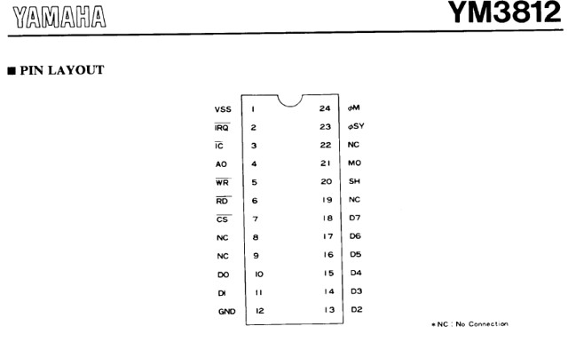
1. Check to make sure the Yamaha keyboard has one of these FM chips (like above), identify the chip number and get the pin outs. The pin outs of interest will be labeled D0, D1, ... D7. There are typically 8 data lines and these data lines connect to another chip in the circuit. For example, the YM3812 chip:

3. With the traces marked or identified, cut them with a razor blade or Exacto knife; this must be sharp and precise. Alternatively, if there are jumpers used, desolder the jumpers and use the existing placement holes for you new connections.

4. With the traces cut it is now time to reconnect the lines with wires and switches. You can solder new connections on the bottom of the board or directly to the pins of the FM chip on top; whatever you are comfortable and experienced with. I use colored wire so each data line has a specific color. This color coding keeps the project organized and easy to reference if additional modifications involve these points.


The remaining 6 connections were soldered carefully to the chip pins.
5. Now connect each color wire to a single switch, a SPDT switch (ON/ON). I keep the FM wires all on the same poles of every data line. This way if other modifications are done it is easy to follow and make connections. Keep the wires together in two bundles with zip ties.


In some cases the keyboard lends well to using patch points. With this patch cables make the connection and this gives the ability of switching, mixing and blending data lines. you can experiment with this once all the new connections are made.

6. With all the connections made, test the modifications and make sure that when the switches are ON the data line from the FM chip to the processing chip is connected. Selecting the switch OFF will disconnect the data and this is where the fun begins. Once all connections are correct, otherwise make the corrections, I usually apply a bead of hot glue to the new soldered points. This way during assembly if the new wires are in a position where they may have a slight stress point they will not become bent or break off.

Disclaimer: I cannot be responsible for the outcome of the modification, you are doing this at your own risk. Circuit bending is part experimentation and part electrical engineering. These modifications made were not intended during the engineering and designing phase from the manufactures, so we each have to take responsibility for our own mistakes, or successes : ) .
